0... -40 dB VU meter by Archy.
Hello.
I found several quad comparators, type LM339 and wondered what could be done with them. A flyback DC converter? Done. Buck converter? Step-up converter? Done. Boring. Something... that would consume several comparators and maybe there would be some nice LEDs, too. Then it hit me. A VU meter, big, beautiful, professional! From that moment started my thoughts flowing. Those VU-meter ICs that are sold in every electronics shop? Maybe ten LEDs. I wanted more, say... 40 LEDs a channel! 1 dB apart. That could be something.
40 LEDs each accompanied by a comparator, reference voltages generated by a chain of resistors. Linear meter would have been easy to make, but a real VU meter has to be logarithmic. Maybe the meter could be used as a power meter in a power amplifier. VU meter uses formula 20log(V/V0) and power meter formula 10log(V/V0). A spreadsheet for calculating those resistors, easy. Other electronics would contain an input stage, ideal rectifying and RC circuit for smoothing the signal after rectifying. The hit the next problem: The RC circuit. If the VU meter would go down to -40 dB, it would take a long time the meter to decay after an impulse. I did some calculations and noticed, that if the meter would work satisfyingly at 25 Hz input signal, the time constant of that RC circuit would be very long. Decaying after a loud impulse would take seconds. Unacceptable.
Well, I included a sample/hold circuit with a digital control. It works as follows: Ideal rectifying finds peaks from the input signal and collects them into a capacitor. That's the sample part. Then the charge from the capacitor will be transfered into another capacitor, that holds its voltage constant while the first capacitor is discharged and another peak value is collected into it. The LED bar shows the voltage of the second capacitor all the time. That way when a short peak comes into the meter it will be viewed on the LED bar and because the first capacitor is discharged completely quite often, the silence after a peak will be viewed correctly.
Another problem: What if a peak comes right when the first capacitor is being discharged? The peak wouldn't show at all. I had to add another sample/hold circuit and make the S/H circuits work together. While S/H 1 transfers its charge to the second capacitor and is discharged, S/H 2 collects the peak value. After a while they switch their jobs. S/H 2 will be transfered and discharged while S/H 1 collects peaks. That way there's always a S/H circuit listening for short peaks. The rate at which S/H circuits operate is controlled by a 555 timer and some 4000-series CMOS logic. Because the operation is strictly controlled by digital logic, it's easy to change the operating speed.
That's about it. The S/H technology used makes the VU meter control part a little complicated, but it's necessary to avoid the slow decay problem.
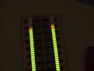
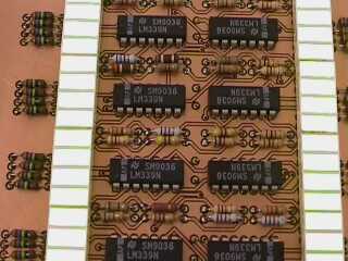
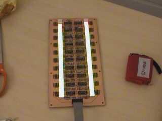
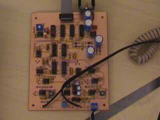
As an apetizer, some photographs of the product. Click to enlarge, as usual.
And some MPG video to really make you interested! MPG1 500 kbps, 5.9 MB, 1:34 The music, by the way, is Vertigo by THC Flatline.
About operating voltages and things like that: Because there are op-amps in the circuit and I wanted to use real earth, double-sided operating voltages are needed. There will be 40 LEDs, 80 in stereo version, and if 10 mA of current flows through each LEDm that makes 800 mA of current. To avoid excess heating I ended up with operating voltages of +/- 8 V. 8 vots, 20 LEDs in series will take about 4 volts, output of LM339 will take about 0.5 volts, 3.5 volts to be dissipated in series resistor. +/- 8 volts is also good for op-amps and 4000-series logic works just fine with that. I decided that 0 dB level is half of that, 4 volts. That gives enough headroom for op-amps and LM339s, that don't work above VCC-2 volts. Plenty of +8 volts is needed for the LEDs. So, solid rectifying, a couple electrolytics and a 7808 regulator are needed. The regulator needs a heatsink, say, a black aluminum plate of 100 mm by 80 mm by 1 mm or equivalent. -8 volts is used only by op-amps and 4053 analog switches. LM339 has common input voltage range down to -0.3 volts thus working fine with single supply. To keep the mains transformer simple the circuit creates the -8 volts with a charge pump and 7908 regulator. This regulator works fine without cooling.
Input amplifier and rectifying, left channel.
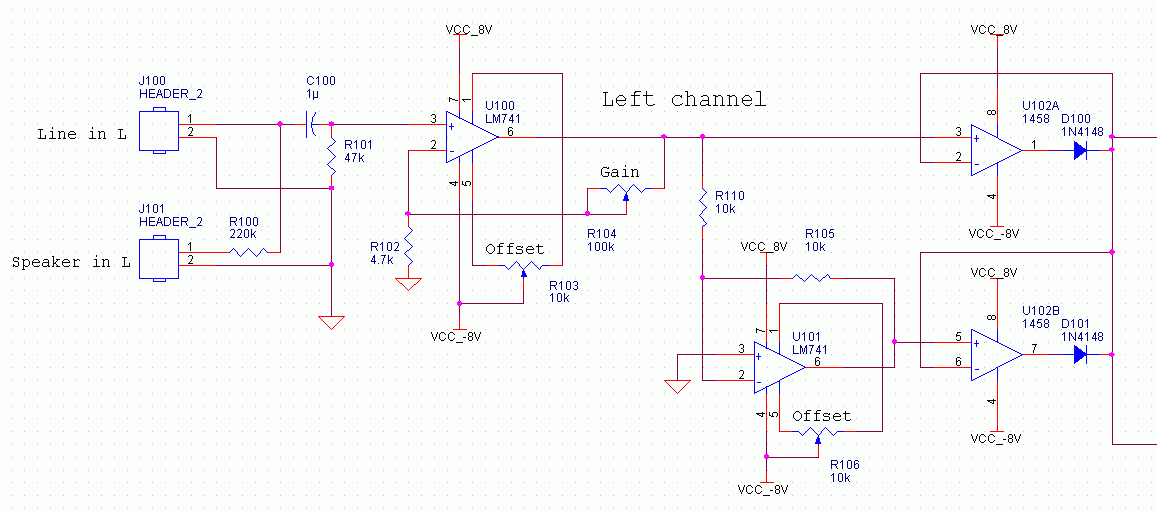
Input connectors, C100 to avoid DC entering the meter. R100 with R101 provides attenuation of about 1:5 for connecting to speaker lines. If you have a powerful amplifier, you may have to increase the value of R100. U100 is non-inverting amplifier with gain adjustable from 1 to about 20 with R104. With gain=1 full scale of the meter is 4 volts peak. Next, U102 does ideal rectifying for positive half of the incoming signal. Negative half is inverted by U101 and rectified by U102. Both rectifiers have low output impedance, suitable for charging the first capacitor in S/H circuit.
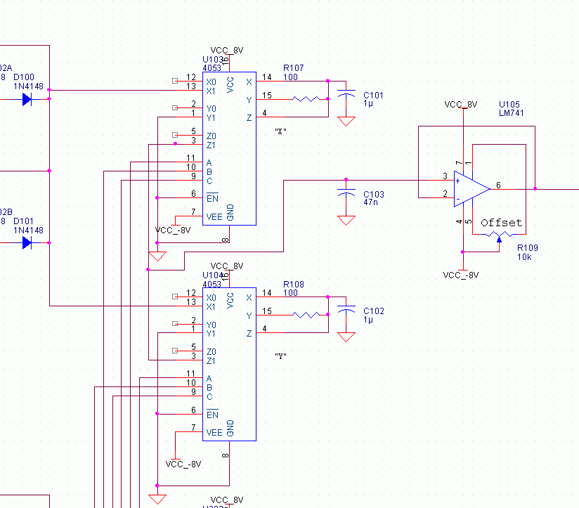
This is the sample and hold circuit for left channel. Because the OrCad drawn circuit is somewhat messy, here's the principle in another form.
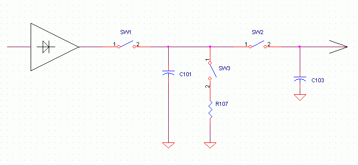
Rectified signal is fed into both triple analogue switches type 4053.
S/H "X", the upper, takes input signal into pin 13. When the switch U103
gets the Collect signal from control logic, SW1 is closed and peaks of the
rectified signal are stored in C101. In the next moment the switch gets the
Transfer signal, SW1 is open and SW2 closed. Tthe charge goes from C101 into
C103. While C101 is 1 µ and C102 is 47 n they have a ratio of
about 20. When two capacitors are connected together, the charges are balanced,
right? When the other capacitor has much smaller capacitance, it has to adjust
itself to the bígger capacitance and that results into that bigger
capacitor's voltage doesn't change much but the smaller will be charged or
discharged to the voltage of the bigger capacitor. Then the switch gets the
Clear signal SW2 opens and SW3 closes. SW2 disconnects C101 from C103 and
SW3 connects C101 to ground via R107. C101 discharges quickly. There are two
of these circuits. U104 does the same things as U103 in the same order but
180 degrees later. That way there's always either of the Collect switches
closed and peaks are stored in C101 or C102, respectively.
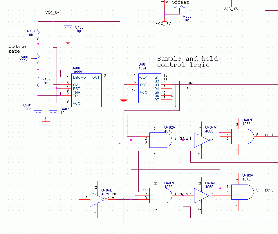
The sample-and-hold circuit consists of a 555 timer with adjustable frequency of about 40...320 Hz. Counter U401 and additional logic creates a sequence of signals. The frequency from 555 timer gets divided by eight resulting in update frequency adjustable from 5 Hz to 40 Hz. The Collect Y signal comes right from the counter, Collect X is the same as Collect Y but inverted. These are the two most important signals. When Collect Y is active, Collect X is not and the "Y" side collects peaks. A moment later Collect Y is inactive and Collect X is active, thus "X" side collects peaks. The Transfer and Clear signals are made of these two and another output of the counter. The principle is that when "Y" side collects, it collects, when it doesn't collect, it transfers, but at the eight moment it doesn't collect nor transfer, it clears. Hope you understood.
The D/A converter and display section:
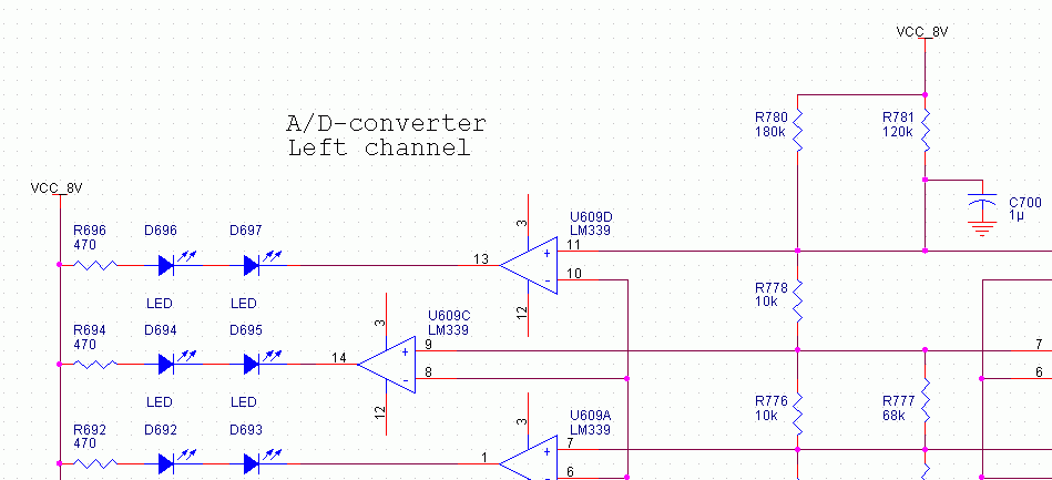
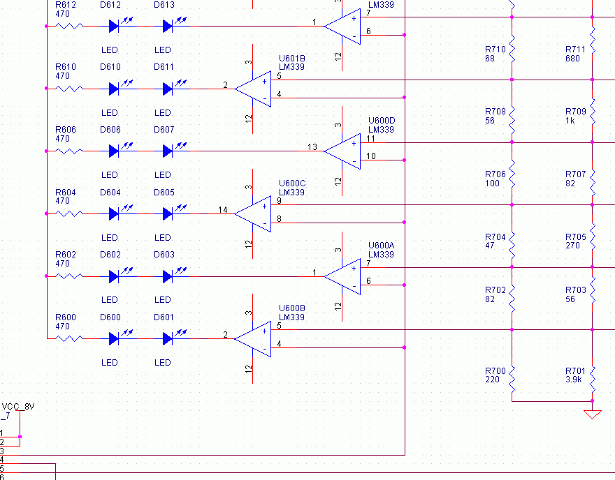
The upper clip is the high end of the comparator chain and lower clip the low end. You can see the resistors on the left. They provide the reference voltages for the comparators. The resistances have been selected by using a spreadsheet and the formula 20*log(V/V0) to create comparison voltages at steps of 1 dB. There are two resistors in parallel in each stage so that 5 % carbon resistors could be used. Usually the 5 % resistors are accurate down to 1 %, but to make the meter actually precise down to 1 % you should check the resistance of the resistors you're using or use 1 % resistors. Using low-tolerance resistors may lead into linearity errors. If tolerances are not so important, ordinary 5 % resistors work just fine.
Here's the Excel spreadsheet in binary form and the same as gif image:
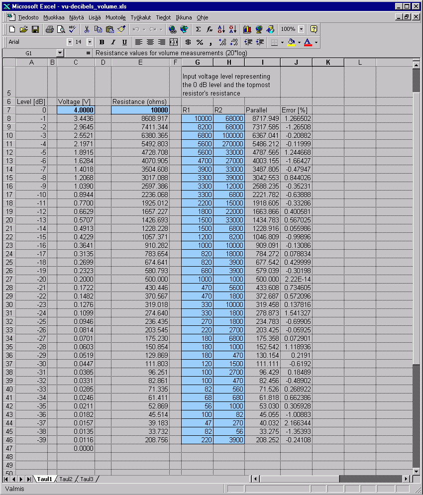
4 volts has been set as 0 dB level. 3.44 volts is then -1 dB, 2.96 volts is -2 dB and so on. First resistance, resistance of R778 has been set to 10 kilo-ohms. All the other resistances are calculated out of these values. The current that flows in the resistor chain is (4.000V-3.4436)/10k = 0.05564 milliamperes. Then, a voltage drop of 3.4436-2.9645=0.4791 volts is needed. 0.4791V/0.05564mA=8.61 kilo-ohms. That can be created by connecting 10k and 68k in parallel. 1/(1/10k+1/68k)=8.717k, that's close enough to 8.61 kilo-ohms. The resistances could be calculated with a calculator but this is one of the tasks that spreadsheets are for. The last voltage drop from 0.0116 volts to 0 volts is done by resistors R700 and R701. So, -39 dB level is 0.0116 volts, that is 11.6 millivolts. The LM339 has input offset voltage of less than 3 mV. If the VU meter would go down to -50 or -60 dB, the offset voltage would prevent it from working. So, this is about the best that can be done this way.
If you would like a PA power meter instead of VU meter, here's the solution. We only change the formula from 20log to 10log. Spreadsheet in binary form and as gif image:
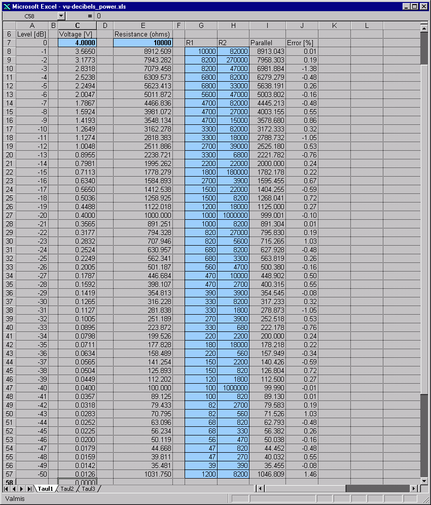
Note that because the steps are smaller in power measurement than in voltage measurement, we could make the meter to go down to -50 dB without violating the 3 mV limit of LM339. You can make the meter as long as you wish bu cutting that table as desired and adjust the lowermost resistors so that the resistor chain's lower end is in the right voltage. For example, if you want the meter to go down to -30 dB, cut the table after row 37 and either edit the spreadsheet to calculate the resistance of the last resistor or calculate these pre-calculated values. From column I you could calculate 317+278+252+222+200+178+157+....+44+40+35+1046 ohms and the sum is the resistance of R700 in parallel with R701. That would create voltage of 316 mV at upper end of R700 and determine the input voltage level at which the first LED will be lit.
Phew. Hope you understood.
You can assign power values for the LEDs. If you have, say, a 100 W amplifier, you input a test signal, attach an artificial load to the output of the amp, connect the VU meter, adjust the VU meter to full display at that power. If you have yellow and red LEDs, adjust so that at 100 W all yellows glow but none of the reds. Then the topmost yellow LED is marked as "100 W". Ten leds downwards, mark "10 W", another 10 LEDs down there's "1 W" LED and so on. If you have any doubts on that, let's check that the calculations are right. What comes to the Meter itself, its 0 dB level is 4.00 volts. Power equals to voltage squared divided by resistance, right? P=V^2/R. When voltage is divided by 10, power is divided by 100. Let's not think about the resistance, it remains constant. If we raise 4 to second power, we get 4*4=16. So, at some circumstances 4 volts would yield to 16 watts. That's the 0 dB level in our spreadsheet. Go 10 dB lower, you find voltage of 1.2649 volts. That squared makes 1.599. So, 10 dB drop in power measurements equals to power being divided by 10. -20 dB would make 0.4*0.4 = 0.16. Yup, that's 1.6 divided by 10.
Phew. Hope yoy understood that, too. :)
There's also a simple microphone amplifier for connecting a microphone.
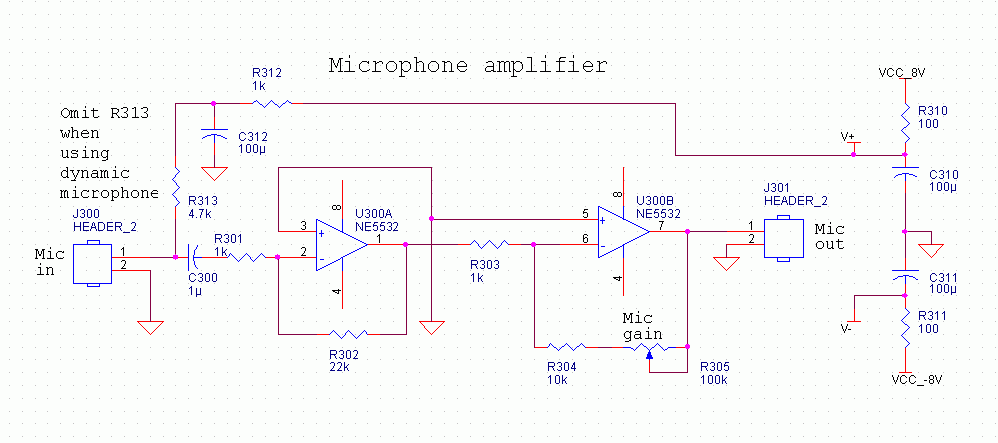
That's quite straightforward. C300 prevents DC entering the amplifier, U300A amplifies it by 22, U300B amplifies it by 10...100 depending on position of R305. Total gain is 22*10=220 ... 22*100=2200. With input signal of 2 mV and gain at maximum the mic amp outputs 2 mV*2200=4.4 V, more than enough. R310 and C310 filter the positive operating voltage, C311 and R311 filter the negative operating voltage. For connecting an electret microphone there is another filter network, R312-C312. That filtered voltage is fed to the microphone by R313. If you use a dynamic microphone, remove R313.
The power supply:
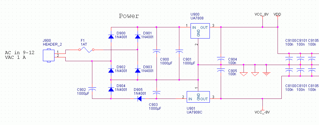
12 VAC is fed into J900. Right after that there is a 1 amp fuse. The meter
needs about 800 mA when all LEDs are lit. If the 1 amp fuse blows after some
use and there's nothing else wrong, that might be that 1 amp fuse isn't enough.
In that case replace it with 1.25 amp. The AC is full-wave rectified by D900-D903,
filtered by C900 and C910 and regulated by U900 to create a stable voltage
of 8 VDC. U900 dissipates heat at power of around 7 watts. Remember to attach
it to substantial heat sink. To prevent the need for center tap in the transformer's
secondary winding the negative voltage is created by a charge pump circuit.
The charge pump creates negative voltage into C903. The voltage is regulated
by U901. Since the need for -8 volts is only around 30...70 milliamperes,
U901 won't need any heat sink. Capacitors C9100.... and C8100.... are bypass
capacitors.
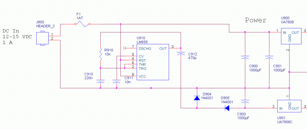
Modified power supply for 12VDC-only supply, e.g. for using in a car. Positive
voltage is taken directly to positive-side regulator. Negative voltage is
created by means of a charge pump. U910 acts as a squarewave generator at
around 400 Hz. C912 and D904 shift the pulses to negative side and
D905 "collects" the negative pulses to C903. The ground pin (1) of the 555
is of course grounded. This circuit is untested,
but it should work.
Download section!
There are problems with the OrCad PCB and schematic file: I'm not able to get the files downloaded from this page opened in OrCad. Perhaps I should include the whole directory tree, but I'm not willing to do that right now. The PS and PDF files work OK.
Schematics in OrCad format, PostScript format and PDF. The PS and PDF files are one A4 paper each and very small print, almost unusable as printed. Quite OK for viewing with AcroRead using magnification of, say, 400 %. I couldn't get better output from OrCad. Of course you do have the schematics as GIF images on this page.
The PCB is double-sided. Both control and adc/display are in one PCB file. The PCB can be cut in two halfs, there are connectors for a 7-pin cable. PCB in OrCad format. Component placement, control part PS or PDF. Component placement, ADC/display part, PS or PDF. The whole PCB in GerberX format: Top, bottom, drill. PCB layout as PDF: Control top, control bottom, ADC top, ADC bottom. Parts list as text file.
Notes on building the VU meter
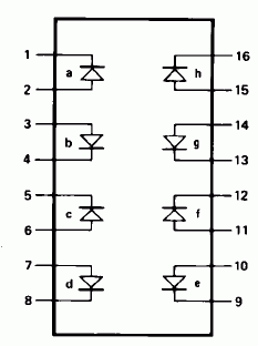
The orientation of the LEDs is somewhat bizarre. Or, well, not so bizarre
if you use the same LED bars as I, HLMP-2820, -2720 and -2620. Green, yellow
and red, respectively. If you're using individual LEDs, take care in putting
them in the correct way.
The microphone amplifier on myt PCBs doesn't seem to work properly. There's too much interference. I think that is because I was lazy and didn't route the ground lines manually. The autorouter didn't make any difference between mic amp ground and digital ground and that is poison for the millivolt-level signals of the mic amp. Maybe by cutting the ground lines and rerouting them with jumper wires would help.
I measured the amplitude response of my prototype. -3 dB lower cut frequency was around 2 Hz, low enough, indeed. Upper cut frequency, however, was around 18 kHz. I think that's mainly because of the old, cheap, slow 741 op-amps that I used. Replacing them with a faster type could improve the VU meter's performance.
Offset null adjustments: There are places for offset trimming potentiometers, namely R103, R203, R106, R206, R109, R209. Power on the meter with no imput signal. Using a millivoltmeter measure voltage between output of U100 and adjust it to zero using R103. The same for U200-R203. Then U101-R106, U201-R206 and finally for U105-R109 and U205-R209. In other words, DC level should be no more than a couple of millivolts all the way. Remember, 12 mV lights the first LED.
I think this is about what I can say about this project to you. Coming
up next: Digital Cuckoo Clock version 2.
Page last updated by Archy 15.6.2004